Advanced NDE Services
Time of Flight Diffraction (TOFD) is widely used in the oil and gas, petrochemical and power generation industries and is even more reliable than traditional radiographic, pulse echo manual UT and automated UT weld testing methods.
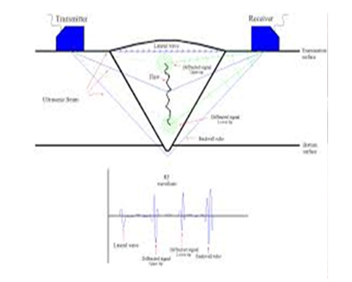
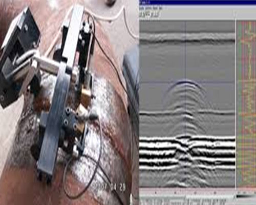
TOFD systems use a pair of ultrasonic probes sitting on opposite sides of a weld-joint or area of interest. The transmitter probe emits an ultrasonic pulse which is picked up by the receiver probe on the opposite side. In an undamaged part, the signals picked up by the receiver probe are from two waves – one that travels along the surface (lateral wave) and one that reflects off the far wall (back-wall reflection).
When a discontinuity such as a crack is present, there is a diffraction of the ultrasonic sound wave from the top and bottom tips of the crack. Using the measured time of flight of the pulse, the depth of the crack tips can be calculated automatically by trigonometry application.
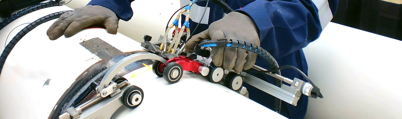
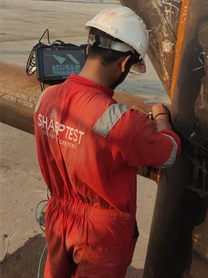
PAUT utilizes multi-element transducers with the capabilities to send an array of sound, in a range of angles, through the material being tested. The multiple-element probes allow for wave forming in a multitude of configurations, providing an enhanced, two dimensional, imaging of discontinuities within material, which is not obtainable with conventional ultrasonic. The inspection results are clearly stored and displayed for reporting.
PAUT can be performed on nearly any homogeneous material, but is most commonly used on steel, steel alloys, and composite materials
Eddy current inspection is one of several NDT methods that use the principal of “electromagnetism” as the basis for conducting examinations. Several other methods such as Remote Field Testing (RFT), Flux Leakage and Barkhausen Noise also use this principle.
Eddy currents are created through a process called electromagnetic induction. When alternating current is applied to the conductor, such as copper wire, a magnetic field develops in and around the conductor. This magnetic field expands as the alternating current rises to maximum and collapses as the current is reduced to zero. If another electrical conductor is brought into the close proximity to this changing magnetic field, current will be induced in this second conductor. Eddy currents are induced electrical currents that flow in a circular path. They get their name from “eddies” that are formed when a liquid or gas flows in a circular path around obstacles when conditions are right.
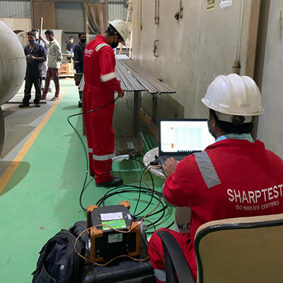
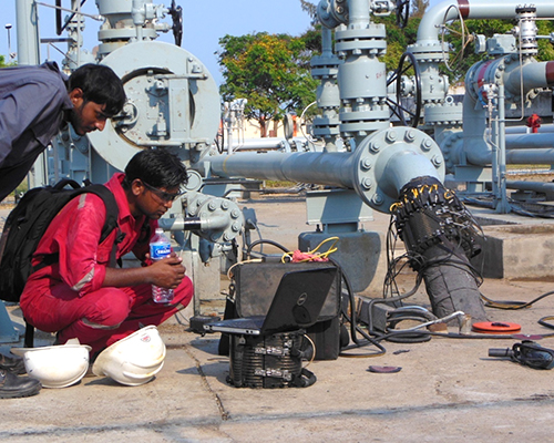
LRUT is one of latest methods in the field of non-destructive evaluation. The method employs mechanical stress waves that propagate along an elongated structure while guided by its boundaries. This allows the waves to travel a long distance with little loss in energy. Nowadays, GWT is widely used to inspect and screen many engineering structures, particularly for the inspection of metallic pipelines around the world. In some cases, hundreds of meters can be inspected from a single location. There are also some applications for inspecting rail tracks, rods and metal plate structures
Advantages :
- Long range inspection - potential to achieve hundreds of meters of inspection range.
- Limited access - insulated line with minimal insulation removal, corrosion under supports without need for lifting, inspection at elevated locations with minimal need for scaffolding, and inspection of road crossings and buried pipes.
- Data is fully recorded.
- Fully automated data collection protocols.
Magnetic flux leakage (MFL) is a magnetic method of nondestructive testing that is used to detect corrosion and pitting in steel structures, most commonly pipelines and storage tanks. The basic principle is that a powerful magnet is used to magnetize the steel. At areas where there is corrosion or missing metal, the magnetic field "leaks" from the steel.
In an MFL tool, a magnetic detector is placed between the poles of the magnet to detect the leakage field. Analysts interpret the chart recording of the leakage field to identify damaged areas and hopefully to estimate the depth of metal loss. This article currently focuses mainly on the pipeline application of MFL, but links to tank floor examination are provided at the end.
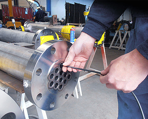
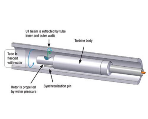
IRIS is an ultrasonic method for the non-destructive testing of pipes and tubes. The IRIS probe is inserted into a tube that is flooded with water, and the probe is pulled out slowly as the data is displayed and recorded. The ultrasonic beam allows detection of metal loss from the inside and outside of the tube wall.
Principle of operation
The IRIS probe consists of a rotating mirror that directs the ultrasonic beam into the tube wall. The mirror is driven by a small turbine that is rotated by the pressure of water being pumped in. As the probe is pulled the spinning motion of the mirror results in a helical scan path.
One of the key settings in the procedure is to ensure that the ultrasonic pulse initiates in the very focus point at the centre of the tube or pipe. An off-centre pulse will show a distorted image of the tube due to the difference in the sound path for either side of the tube wall. For that reason, there are cantering devices that help the operator to keep the turbine cantered at all times.
The transducer utilized for the inspection has to be fast (frequency) enough to bounce back at both inner wall and outer wall. For the very smallest and thinnest tubes it is usually used a 25Mhz piezoelectric transducer.
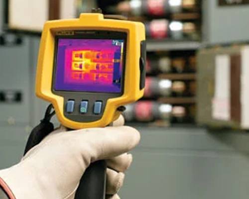
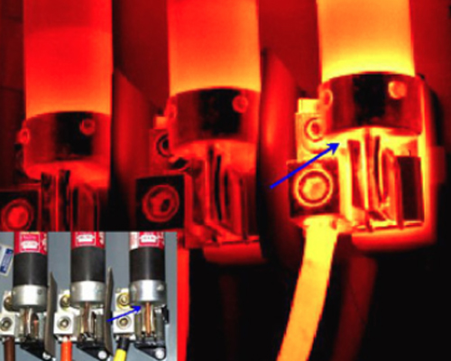
Infrared thermographic cameras produce images of invisible infrared or "heat" radiation and provide precise non-contact temperature measurement capabilities. Thermal or infrared energy is light which is not visible because its wavelength is too long to be detected by the human eye: it's the part of the electromagnetic spectrum we perceive as "heat". Thermography is the use of an infrared imaging and measurement device to "see" and "measure thermal energy emitted from an object.
Infrared testing is essentially a non-invasive, non-destructive inspection process that uses thermography cameras. These devices gather temperature signatures that lie far beyond the range of visible light. Grattan Infrared analysis this data to help us detect problems before they become serious and become costly issues.
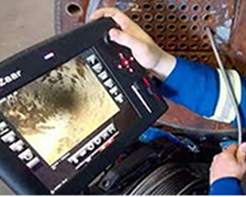
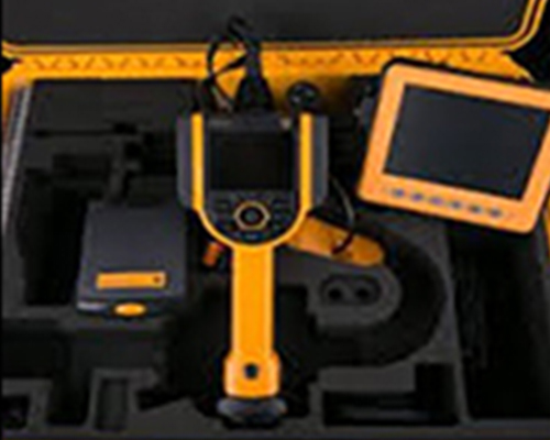
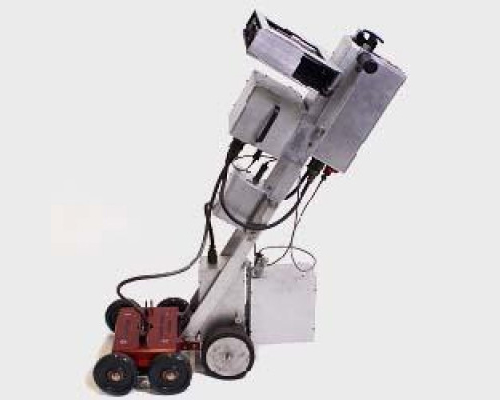
RVI or RDVI, refers to a specialty branch of non-destructive testing (NDT). RVI/RDVI is an enhanced visual examination method that facilitates acquisition of visual data by means of visual aids including but not limited to video borescopes, push cameras, pan/tilt/zoom cameras and robotic crawlers. It is commonly used where distance, angle of view and limited lighting may impair direct visual examination or where access is limited by time, financial constraints or atmospheric hazards.
The "remote" portion of RVI/RDVI refers to the characterization of the operator not entering the inspection area due to physical size constraints or potential safety issues related to the inspection environment.